1978 Shovelhead Rocker Box Rebuild

Tight & Right

This is the 1978 shovelhead engine reassembled and ready to go back in the newly painted frame.Street Chopper Staff

This story originally appeared in an issue of Street Chopper.

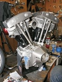
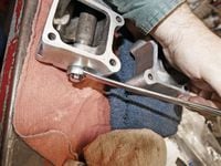
A friend of ours is building a shovelhead chopper from parts and pieces that he has gathered over the past few months. Swap meets, friends, and word of mouth leads have brought most of the parts needed for the chop into a small one-car garage. A big twin swingarm frame with a weld-on hardtail section forms the basis for the new bike. A 1978 shovelhead engine was found, hauled home, and mounted into the completed frame. From this point on, the rest of the components were added until a running mock-up rolled out of the garage and into the sunshine. The engine was supposed to be “fresh,” but once fired up, the resultant top-end noise and the growing puddle of motor oil told a different story. The oil leak was from the open port in the engine cases for the primary oil feed. A simple pipe plug fixed the oil leak and the noise originating in the top end (i.e. the rocker boxes). The rest of the engine sounded OK, but we decided to check it out once the mock-up was completed.

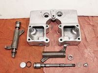
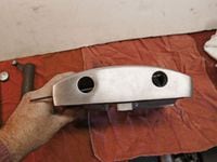
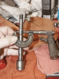
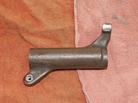
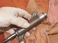
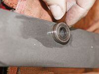
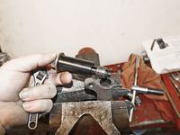
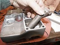
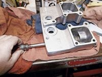
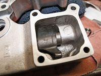
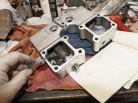
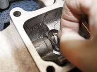
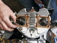
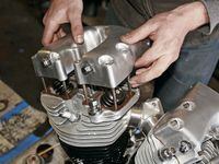
Once the engine was out of the frame we mounted it on an engine stand and removed the top end for a look-see. The pistons and rings looked and measured out in the allowable tolerances, same for the valves and guides; they in fact did look "fresh". The rocker boxes were another story: the bushings in the rocker arms were worn pretty bad, and the tips of the rocker arms that push on the valve stems were grooved and pitted; all four rocker arms needed to be resurfaced. The other factor that contributed to the noise we heard was the excessive amount of endplay between the rocker arms and the rocker box. The factory specifications called for .004-.025-inch. In two rocker arm locations we had over .035-inch endplay, and as far as the rest of the rocker arms we had almost the maximum allowable end play.

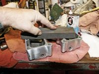
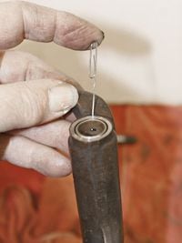
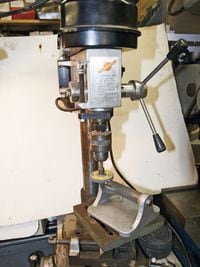
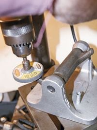
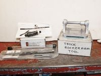
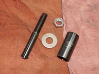
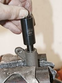
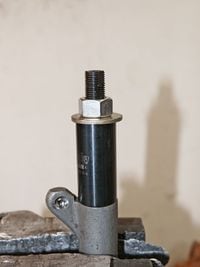
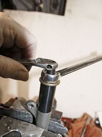
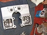
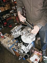
The above description of the ’78 rocker boxes may sound like a mess, but it really is not that big of a deal to fix. We’ll describe how we went about rebuilding the rocker box assemblies for a quiet, oil-tight operation. There are some special tools you will need in order to perform this task correctly. The tools are not that expensive, especially if shared with a couple of friends; in fact, some of the tools cross over to Sportster, Evo big twin, and twin cam model rocker arms, also.

Here is one (front) of the shovel's rocker boxes and associated components. Front intake rocker arm assembly (A), front rocker box (B), front exhaust rocker arm (C), rocker arm shaft plug (D), rocker arm shaft O-ring (E), rocker arm shaft (F), rocker arm spacer (G), rocker arm shaft end cap washer (H), rocker arm shaft end cap nut (I).Street Chopper Staff
A thorough cleaning of all parts was the first step in determining what needed to be done to bring the rocker boxes back to full service condition. After cleaning, we checked the oil passages with a long drill bit to ensure they were clear and we chased the threaded holes, including the oil line fitting holes.Street Chopper Staff
The last step for the rocker boxes was to stone the gasket surface to remove any dings or burrs that may cause an oil leak. We then cleaned the rocker box again to remove any residue from the stoning process, and then set it aside while we checked out the rest of the parts.Street Chopper Staff
Next we turned our attention to the rocker arm shaft. Using a micrometer, we measured each of the shaft diameters where the rocker arm bushings ride. We measured each of the journals in several different locations; any difference more than .001 on any journal is reason to replace it. We also checked the shaft between centers to ensure the shafts were straight.Street Chopper Staff
The rocker arm transfers movement from one side of the engine to the other. The pushrod pushes on the socket side (A), which pivots the arm on its shaft, allowing the opposite side of the arm (B) to push on the valve stem, opening the valve in the combustion chamber. The rocker arm rotates on the rocker arm shaft on two brass bushings, one at each end of the arm (C).Street Chopper Staff
To check the fit of the rocker arm bushings, insert the shaft in the rocker arm in the same direction as it runs (big end of shaft next to pushrod end of rocker) and try to move the rocker arm on the shaft.Street Chopper Staff
Here is another view of the shaft in the rocker arm. The rocker arm bushing (A) should be a nice rotating fit on the shaft's (B) journal. The back-and-forth movement should be no more than .0035(C).Street Chopper Staff
During the inspection of the rocker arm (make sure that the oil passage hole in the rocker arm is aligned with the oil hole in the bushing), we wanted to physically see the open passage, so we used a paper clip passed through the oil passage.Street Chopper Staff
We determined that our rocker arm shafts were in good shape, but the bushings were worn past their limits and need to be replaced. There are a couple of ways to remove the worn bushings. While the rocker arm was clamped between the soft jaws into the bench vise, we threaded a 9/16-18 tap into the bushing a few turns.Street Chopper Staff
Once the tap had a good bite into the bushing, we rotated the rocker arm in the vise and used a brass drift inserted in the opposite end of the rocker arm, then we gently tapped the bushing out of the rocker arm.Street Chopper Staff
Again, to remove any burrs, we like to "rub" the ends of the rocker arms on the stone before installing the new rocker arm bushings.Street Chopper Staff
We like to start with the valve-stem side of the rocker arm when installing the new bushings, because this is the side where the oil holes need to be aligned. There is a slight chamfer on each end of the rocker arm, which helps to start the new bushing into the rocker arm.Street Chopper Staff
We used the bench vise to push the new bushings into the rocker arms, making sure to keep the "soft jaws" in place so the bushings or the arms are not damaged and use a small socket or bearing driver (arrow) to push the new bushing in flush with the end of rocker arm.Street Chopper Staff
OK, the new bushings were pressed into the arm, now they needed to be sized to the rocker arm shaft. We sized the bushings with a reamer made specifically for the task. We clamped the rocker arm in the bench vise by the pushrod end of the arm, and then slid the reamer into the arm until the cutting edges started to cut the bushings. The reamer was then rotated (using a suitable wrench) as a slight, forward pressure was exerted on the reamer at the same time.Street Chopper Staff
When using a reamer, be sure to rotate it only in a clockwise direction, never rotate it backwards, as it will dull the cutting edges. Here you can see the cuttings (arrow) of the bushings in the flutes of the reamer as they emerge from the rocker arm.Street Chopper Staff
After the reamer has been passed through the bushings in the rocker arm, blow out any shavings or cuttings with compressed air and reinsert the rocker shaft for that particular rocker arm and check that the arm rotates freely about the shaft.Street Chopper Staff
While still at the bench, we stoned both sides of the rocker arm shaft spacer, again, to remove any burrs on the spacer's flat surfaces.Street Chopper Staff
The last task to complete the refurbishment of the rocker arm was to dress the tip that pushes on the valve stem. To resurface the tip we used a specially designed tool from Ron Trock's shop. The Trock tool is used in conjunction with a drill press (as shown), the rocker arm was mounted on the spindle of the tool and held under a rotating grinding stone on the drill press.Street Chopper Staff
The pushrod side of the rocker arm is connected to a spring (as shown) to provide tension on the arm. To use the tool, turn on the drill press and position the tip of the arm under the spinning stone and lower the quill of the drill press with the arm in a smooth even motion. Try not to let the stone stay in one spot on the rocker arm tip, since that will grind a flat spot on the tip. Check your progress frequently; the tip of the rocker arm has been hardened about .025 deep, so you only want to grind the tip until any pits or groves have been eliminated.Street Chopper Staff
Here are the tools we used for refurbishing our set of shovelhead rocker boxes: 9/16-18 Craftsman tap (A), rocker arm bushing reamer (B), rocker arm bushing remover (C), Trock rocker arm grinding fixture (D), plus, of course, the normal assorted hand tools.Street Chopper Staff
The bushing removal tool comes with the parts seen here, along with instructions. The mandrel and pin (A), sleeve (B), flat washer (C), and nut (D).Street Chopper Staff
When using the tool it's helpful to secure the rocker arm in a bench vise. Insert the mandrel into and past the lower edge of the bushing. Now, insert the pin through the mandrel.Street Chopper Staff
Slide the sleeve (open-side down) over the mandrel and center it on the end of the rocker arm.Street Chopper Staff
Next, place the washer over the threaded portion of the mandrel and thread the nut onto the mandrel, making sure that the pin inside the mandrel is still in place and hand-tighten the nut.Street Chopper Staff
Machined on the threaded end of the mandrel are a pair of flat surfaces for a wrench to hold the mandrel while the nut is tightened onto the mandrel, thus pulling the mandrel up out of the rocker arm and bringing the old bushing with it.Street Chopper Staff
The operation is a success. Just seven more rocker arm bushings to go.Street Chopper Staff
Time to assemble all the rocker arm components and check for the rocker arm end play. We slid the correct rocker arm in its location of the rocker box.Street Chopper Staff
We inserted the rocker arm shaft through the rocker box, the rocker arm, spacer, and on through the other side of the rocker box.Street Chopper Staff
Here is the inside of the rocker box showing the correct location of the rocker arm and spacer. The spacer fits back into a recess (arrow) on the inside of the box.Street Chopper Staff
Next, we placed the end washer and nut on the threaded end of the rocker arm shaft and tightened the nut to draw the rocker shaft tight into the rocker box. Then we reached inside the rocker box with a finger to make sure the rocker arm rotated freely and that it had some end play.Street Chopper Staff
Using a set of feeler gauges, we measured the amount of end play between the rocker arm and the spacer. The rocker arm should still continue to rotate freely with the proper feeler gauge between the arm and the spacer; it helps to keep a pad of paper nearby to record the measurements.Street Chopper Staff
The smallest amount of end play allowed is .004, so we subtracted .004 from our feeler gauge measurement, and theoretically that is the amount of shims we need. If we can come up with a selection of shims that comes close then we'll roll with them; anywhere up to .008 of end play would be acceptable. If there is more than one shim required to set the correct end play, we split the shims on either side of the rocker arm. Here we put one shim on the shaft before reassembling the box to check end play.Street Chopper Staff
The remaining shims fit between the rocker arm and the spacer. When assembling the left-side shims, we made sure the shims were centered on the shaft. If the shims are not centered, the rocker arm will lock up and not move freely. When everything was assembled and tight, we rechecked the end play with feeler gauges to be sure that the end play was correct.Street Chopper Staff
Up to this point, we did all the procedures dry, with no lubrication to throw off the measurements. Now that all of the parts, rocker arm, shaft, spacer and box have been massaged and are happy, everything comes apart and receives a generous coating of Permatex assembly lube and then back together for the final time.Street Chopper Staff
After final assembly, the right-side rocker arm shaft end plugs and O-rings were installed and snugged down.Street Chopper Staff
Back at our friend's garage where the rest of the engine waited, we sprayed the new rocker box gaskets with Copper-cote gasket sealer. While the Copper-cote was setting up on the gasket, we coated the gasket surface on the head and the rocker box with a thin coat of Copper-cote as well.Street Chopper Staff
Hint: Take your time fitting the gasket over the rocker box mounting studs on the head so as not to tear the gasket. Look the gasket over to be sure that it's centered on the gasket surface.Street Chopper Staff
We put a smear of grease on the tips of the valve stems and on the tips of the rocker arms and slid the rocker boxes down over the mounting studs, making sure the box sat flat on the rocker box gasket.Street Chopper Staff
Each of the nine 5/16-nuts that hold the rocker box to the head were torqued to 15 lb-ft in an X-pattern. We started with the four middle nuts and worked our way outward, saving the "short" nut (number nine) for last.Street Chopper Staff
Once the rocker boxes were bolted down tight, we cinched up the rocker shaft end cap bolts. Then we were ready for the pushrods and covers. We assembled the oil feed lines as we fitted the rocker boxes.Street Chopper Staff